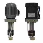
Pneumatic Seismic Pressure Gauge – YPQ-01-Z/25B
Pressure Transmitter lodelYPQ-40 YPQ-25YPQ-25B YPQ-60BYPQ-40AYPQ-70C YPQ-01-Z/40 YPQ-01-Z/25B YPQ-01-Z/105 YPQ-01-Z/70A YPQ-01-Z/40B/ YPQ-01-Z/70A
I. Overview
YPQ-01-Z/40, YPQ-01-Z/70A, YPQ250B, YPQ400B pneumatic seismic pressure reducers are developed for the pressure detection of risers and casings in oil drilling operations. It has the advantages of high precision, good vibration resistance, and natural explosion resistance. Therefore, it can be used for pressure detection in various harsh environmental conditions.
2、 Main technical data
Accuracy levels of 1.0 and 1.5
The gas source is compressed air that removes impurities such as dust, oil, and water, with a rated pressure of 0.35Mpa and a dew point temperature at least 10 ℃ lower than the instrument temperature.
The measurement range is 0-25, 0-40, and 0-70Mpa.
The output pressure signal is 0~0.2Mpa.
The working environment temperature is -10~+70 ℃.
The relative humidity of the surrounding air should be less than 95%.
3、 Working principle
When the air source with a pressure of 0.35Mpa enters chamber A and there is no measured signal pressure, valve needle 4 closes and the air is sealed in chamber A. At this time, the output pressure of the gauge is zero.
When the △ P λ measurement signal pressure is added, this pressure signal acts on the measuring rubber piece 6, causing deformation of the rubber piece. The diaphragm assembly 3 is pushed upward by the piston rod 5. First, the air release valve is closed to prevent the air in chamber B from being discharged into the atmosphere, and then it continues to rise. The valve needle 4 is opened, and the air in chamber A flows into the output chamber B, generating a downward thrust on the diaphragm group 3 to overcome the upward thrust of the piston 5, until the force acting on the diaphragm group 3 and the signal acting on the rubber piece 6 are balanced. At this time, the pressure in chamber B is the output pressure △ P ο of the transmitter.
4、 Instrument usage and adjustment
1. Instrument usage
Before putting the instrument into operation, it is necessary to check whether the connection circuit of the instrument is correct, and then connect it to a gas source with a pressure of 0.35Mpa. After completing the above work, the instrument can be put into operation.
2 Instrument adjustment
Firstly, connect the air source with a pressure of 0.35Mpa to the instrument, and then use a piston pressure gauge to add a force measurement signal, so that the output pressure is △ P ο. When the output signal is lower than the standard value, first loosen the locking nut 1, then adjust the valve seat 2 to rotate to the right to increase the output pressure signal, and then tighten the locking nut. Otherwise, the seat should be rotated to the left at high speed to reduce the output.
5、 Instrument unboxing and installation
1. Instrument unboxing
Before opening the box, the water tank should be checked for any damage. If any damage is found, it should be noted on the acceptance form and reported to the transportation department.
The unboxing of instruments should be carried out according to the following procedure:
⑴ Open the box lid (note the upward mark ↑).
Remove the filling around the instrument and take out the instrument along with the plastic.
2 Installation
⑴ Instrument air source, output pipe joint 01 type is internal thread M16 × 1.5; YPQ250B and YPQ400B measure thread Z 1/4 and output thread Z 1/8.
There are two types of installation pipes for the ⑵ type meter: the external thread Z2 “of the cone pipe and the internal thread Z1 ‘of the cone pipe.
YPQ250B and YPQ400B tables.
6、 Instrument maintenance
1. Under normal installation and operating conditions, the instrument does not require special maintenance.
2. It is recommended to check the accuracy once a year.
3. During instrument maintenance, the interior of the instrument should be cleaned to remove dust. (Note that the large diaphragm group 3 should not be disassembled to avoid affecting accuracy). During assembly, the piston rod 5 should be coated with an appropriate amount of No.2 clock oil to check the accuracy of the instrument and adjust the zero point accordingly. It is recommended to check the accuracy again before putting the instrument into operation to avoid changes in the zero point of the instrument caused by poor fit.

-
 Pick up from the HDE Store
-
") Courier delivery
Courier delivery